
Analysis Shock Phenomenon on Static Diving Test of Diesel Electric Submarine
DOI:
https://doi.org/10.30649/baitaengineering.v2i2.57Keywords:
Submarine’s Static diving.Abstract
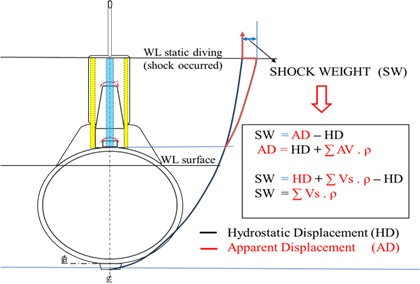
In the series of disel electric submarine construction, the crucial activity is post-ship launching test. Harbor Acceptance Test (HAT) is a function test of equipment, systems, and integration between systems. While Sea Acceptance Test (SAT) is a test to record and file the posture, character, and operational capabilities of submarine. In the SAT series, static diving (SD) tests are scheduled at an early stage. The purpose of the SD test is to determine the posture of the riel submarine versus the design, i.e. stability. Another thing in the data from this test is the ship's tightness, data riel load (DWT), the penetration of equipment that penetrates pressure hull such as stern tube, hydroplanes, hoistable mast, torpedo tube, compressed air bottles, hydraulic line, electrical insulation resistance, as well as sensors equipment (communication, sonar, UWT, echosounder, navigation, speedlog, sonar and radar). The goal is to ensure the safety of the ship and crew in the next SAT stage. In static diving tests, there is always a shock phenomenon where the submarine loses buoyancy and falls with the angle of trim to aft. Efforts by blow out the compensating tank (CT) for recover the submarine is not effective even late until the submarine sat on the seabed. This has an impact on the suction line by mud sediments to the seawater cooling system, also potentially damaging ship equipment: sensors, hydroplane and propeller. The shock is caused by the apparent buoyancy of the equipment in the bridge (sail) area that exposed to the atmosphere, where when entering the final stage of ST, the apparent buoyancy changes instantly to weight force. So there is a submarine imbalance, namely weight exceeds buoyancy and LCB exceeds LCG. This thesis uses quantitative research with Fault Tree Analysis (FTA) method to identify the source of the shock, the weight value of the shock, the initial angle of the shock (trim to stern), terminal velocity, either efforts and solutions to eliminate the imballance in order to achieve the efficiency and effectiveness of the static diving process, as well as safety to continue the series of submarine SAT tests.
Downloads
References
Adolph, Ralph. 2016. “済無No Title No Title No Title.” : 1–23.
As, D N V G L. 2015. “RULES FOR CLASSIFICATION Inland Navigation Vessels Part 1 General Regulations Chapter 1 General Regulations.” (December).
Bureau Veritas. 2016. “Rules for the Classification of Naval Submarines.” 33(Eylül): 528.
Carlberg, Henrik. 2011. “Concept Design of a Commercial Submarine.”
Constable, Anthony. 2018. “PAYLOAD VOLUME OPTIMIZATION FOR SUBMARINE CONCEPT DESIGN NAVAL POSTGRADUATE By.”
DNV GL. 2015. “Part 3 Hull Chapter 15 Stability.” (October).
DNV GL AS. 2015. “RULES FOR CLASSIFICATION Naval Vessels Edition Part 4 Sub-Surface Ships.” (December).
“DNVGL-RU-NAVAL-Pt4Ch1.Ic8I7i8N.Pdf.”
Gabler, Dipl Ulrich. 1924. “Submarine Construction.” Journal of the American Society for Naval Engineers 36(4): 675–675. doi:10.1111/j.1559-3584.1924.tb05502.x.
Gebreselasie, Daniel. “Mechanics and Oscillations: University Physics I.”
Gl, D N V. 2015. “RULES FOR CLASSIFICATION Underwater Technology Part 5 Types of UWT Systems Chapter 7 Remotely Operated Vehicles.” (December).
Jackson, Harry A. 1992. “Fundamentals of Submarine Concept Design.” Transactions - Society of Naval Architects and Marine Engineers 100: 419–48.
Pandeiroth, Novry Noldy. 2015. “Universitas Atma Jaya Yogyakarta.” Ekspedisi: 1–6.
Renilson, Martin. 2015. APPLIED SCIENCES AND TECHNOLOGY Submarine Hydrodynamics.
Royal, T H E, and Naval Architects. 2008. WARSHIP 2008 : NAVAL SUBMARINES 9 3D Visualisation & Human Machine Interaction Submarine Rescue Systems.
Streeter, V. L., and E. B. Wylie. 1979. “Fluid Mechanics (Seventh Ed.).”
Sutiyo, Ahmad Nasiruddin, I. Ketut Aria Pria Utama, and Bagiyo Suwasono. 2024. “Numerical Analysis of Drag Characteristics of 209 Submarine with Various Roughness Distribution.” Nase More 71(2): 54–65. doi:10.17818/NM/2024/2.2.
(20041130 052 n.d.)(Adolph 2016; As 2015; Bureau Veritas 2016; Carlberg 2011; Constable 2018; DNV GL 2015; DNV GL AS 2015; DNVGL-RU-NAVAL-Pt4Ch1.ic8I7i8N.pdf n.d.; Gabler 1924; Gebreselasie n.d.; Gl 2015; Jackson 1992; Pandeiroth 2015; Renilson 2015; Royal and Architects 2008; Streeter and Wylie 1979; Sutiyo et al. 2024)
Published
How to Cite
Issue
Section
License
Copyright (c) 2025 BAITA Engineering: Journal of Naval Architecture and Marine Engineering

This work is licensed under a Creative Commons Attribution-NonCommercial 4.0 International License.


